Computer network is a system consisting of computers and other network devices that work together to achieve a common goal. The purpose of the computer network are:
* Sharing of resources: for example, shared use of printers, CPUs, memory, hard drive
* Communication: for example electronic mail, instant messaging, chat
* Access to information: for example web browsing
In order to achieve the same goal, each part of the computer network and provide service request (service). Party requesting the service is called a client (client) and that provide services called the servant (the server). This architecture is called client-server systems, and is used in almost all computer network applications.
Classification Based on the scale:
* Personal Area Network (PAN)
* Campus Area Network (CAN)
* Local Area Network (LAN): a computer network that connects a computer to another computer with a limited distance.
* Metropolitant Area Network (MAN): principle the same as LAN, only the larger distance, ie 10-50 km.
* Wide Area Network (WAN): the distance between cities, countries, and continents. This is the same with the Internet.
* Global Area Network (GAN)
Based on the function: Basically every computer network is functioning as a client and server. But there is a network that has a dedicated computer as a server and the other as a client. There is also a computer that has no special function as a server only. Therefore, based on their function there are two types of computer networks:
* Client-server :
Network is the computer with a dedicated computer as a server. A service / service can be provided by a computer or more. An example is a domain like www.detik.com lots served by the web server computer. Or it could be a lot of service / services provided by a single computer. Examples are jtk.polban.ac.id server that is a multi-service computer with the mail servers, web servers, file servers, database servers and others.
* Peer-to-peer :
Namely computer networks where each host can be a server and also a client simultaneously. For example in the file sharing between computers on the Windows Network Neighborhood Network have 5 computers (we give the name of A, B, C, D and E) that provide access rights to the files they have. At one point A to access the file share of B named data_nilai.xls and also gives access to the file soal_uas.doc C. When accessing a file from B then A serves as a client and as a give file access to C then A serves as a server. Both functions were performed by the same A network like this is called peer to peer.
Based on network topology, computer networks can be divided into:
* Topology bus
* Topology stars
* Topology ring
* Mesh topology
* Topology tree
* Linear topology
Based on the criteria, the computer network can be divided into 4, namely:
1. Based on the distribution of sources of information / data
- This network centralized network consisting of Client and server computers which Client computer that serves as an intermediary to access sources of information / data derived from a single server computer
- Network is a combination of several distributed centralized network so that there are several computer servers that are interconnected with the Client to form a specific network system.
2. Based on geographic coverage can be divided into:
- Network LAN is a network that connects 2 computers or more in coverage such as laboratories, offices, and in 1 cafe.
- MAN network is a network that includes a big city and its local area. Examples of local telephone networks, cellular telephone systems, as well as some ISPs relay network Internet.
- Network WAN is a network with coverage throughout the world. PT network example. Telkom, PT. Indosat, as well as GSM networks such as Cellular Satelindo, Telkomsel, and much more.
3. Based on the roles and relationships of each computer in the data processing.
- Network Client-Server In this network there are 1 or more server computers and client computers. Computers will be computers or servers to client computers and altered through the protocol software on the network. Client computer as an intermediary to be able to access data on a server computer and the server computer to provide information needed by the client computer.
-Network Peer-to-peer in this network there are no client computer or server computer because all computers can make sending and receiving information so that all computers function as clients as well as a server.
4. Based on the data transmission media
- Wired Network (Wired Network) In this network, to connect one computer to another computer in the form of necessary liaison network cable. Function in the network cable to send information in the form of electrical signals between the network computer.
- Wireless Network (Wireless Network) is a network with the medium of electromagnetic waves. In this network does not need a cable to connect between computers that use electromagnetic waves to send signals between the computer information network.
About Networking
Posted by
bryan
comments (1)
Networking is an inter-computer network that connects one computer to another network. to construct this network, the network required the planning of the built called topology. scope of the network itself is divided into three, namely LAN, WAN, and MAN. Devices needed to support such a network the network card.
WWW or Web, is a system where the information in the form of text, images, sounds, and others presented in the form of hypertext and can be accessed by software called a browser.
Local Area Network (LAN) is the number of computers that are connected together in one particular area that is not so large, as in an office or building. Broadly speaking there are two types of network or LAN, a network of Peer to Peer and Client-Server networks. In peer to peer network, every computer connected to the network can act both as a workstation or server. Whereas the client-server networks, only one computer that served as servers and other computers acting as workstations.
Metropolitan Area Network (MAN) is a network in a scale of a city within a city network with high-speed data transfer, which connects various locations such as campuses, offices, government, and so on. MAN network is a combination of several LAN.
WLAN (Wireless LAN) is a new technology that can be considered as additions or replacement of the functions of the existing LAN network so users no longer limited by LAN cables to be entered into the network. By using WLAN is a lot of benefits such as mobility, flexibility, productivity and scalability, and of course there are many other benefits.
How to Install Mikrotik Server
Posted by
bryan
comments (1)
The first step to install this router is by smiling, always joking
with colleagues, laugh hard until finally cried aloud as many as 10 times "THIS IS VERY EASY"
After various complications in the wireless, it's time we change the
server, use proxy jaylangkung.com side to management
bandwidth and router.
Here will be discussed from the speedy bandwidth management, so the ADSL modem
RJ45 cable down and into the LAN computer that has been installed
mikrotik
First time to be on a computer server set up is minimal with
specifications :
1.Processor PII
2.Memory 128
3.NIC (Lancard) 2 pieces
4.Hardisk minimum 1 GB
5.CD room
Step 1 :
Start download Mikrotik, download the ISO here : www.mikrotik.co.id/download.php (click mikrotik-4.2.iso)
Step 2 :
Then burn the CD, burning Image
Step 3 :
After that, insert the CD that had been loaded into the proxy server computer
then turn on the computer.
Step 4 :
Wait until the computer appears as below :
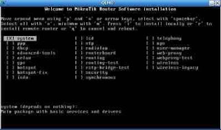
Step 5 :
After that press the 'a' (without quotes) to install all the facilities
contained in mikrotik
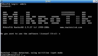
Step 6 :
Let it go, because the installation is in progress, starting from
formatting disks until the installation is complete, if the display appears as in
following the installation has finished.
Step 7 :
After the process is complete, download mikrotik is innate tool, (Winbox) can in
download here : http://www.mikrotik.co.id/getfile.php?nf=winbox-2.2.11.exe
Step 8 :
After that plug the cable from the ADSL modem to one computer Lancard
which has been installed mikrotik
Step 9 :
Then the second LanCard to a HUB / Switch to the local network.
Step 10 :
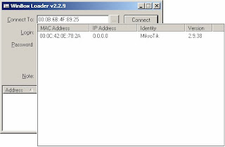
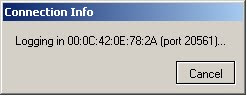
Installation has been completed, now the remote server computers that have been in
installation on top with Winbox which we downloaded, by using
Other computer
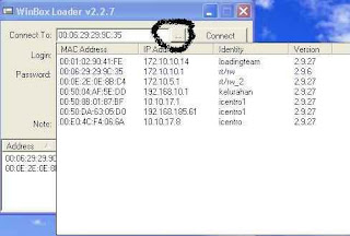
Step 11 :
Select a router that we had installed, its default identity mikrotik, username
admin, password blank

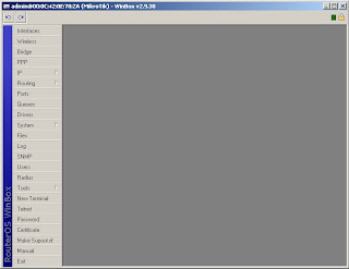
Step 12 :
Select the menu interface, if it has run correctly, it will appear 2
fruit Lancard interface.
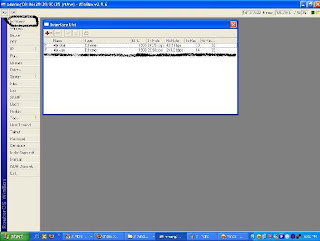
Step 13 :
Double Click on one interface that refers to the local and name Local
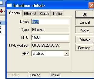
Step 14 :
In the same way, which refer to Interface naming modem Public
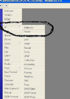
Step 15 :
After that, select the menu IP address

Step 16 :
Display appears as below, then press the plus + button in the left corner
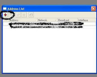
Step 17 :
Add addressnya Ip, for example:
Speedy Modem IP 192.168.1.1, then the proxy IP: 192.168.1.2/24
and named
then press the plus + button in the left corner, then add the IP
address other Lancard
eg local Ip at 10.10.10.1, then enter the IP address
10.10.10.1/27, numbers / 27 to 30 host IP,
Step 18 :
After that select IP and then select the sub menu Routes
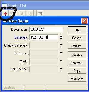
Step 19 :
Then enter its IP gateway, by pressing the plus + in
her left hand corner of the Modem IP 192.168.1.1, then press the OK button
Step 20 :
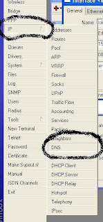
After all the above steps completed, the next step is to fill the control
menu by IP> DNS
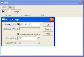
Step 21 :
Select Settings and enter the IP dns, with the primary DNS 202.134.1.10
(default speedy) are both secondary DNS 202.134.0.155 (DNS speedy)
Step 22 :
Once completed the final stage you have to do, which makes the rule for
can be used locally. This very important stage, where communication
LanCard 1 with LanCard 2 placed here. The essence of the above settings on
this stage, it should not be confused
Step 23 :
Choose IP> Firewall> NAT> General
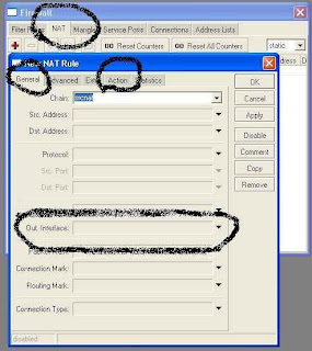
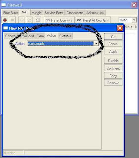
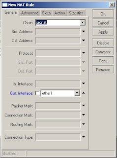
Step 24 :
Chain = srcnat, Out interface = Public (interface we have been given
public name) and then select the action = masquerade and press the OK button
to end
Step 25 :
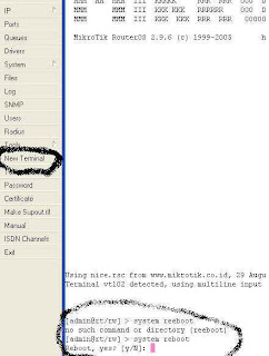
do restart the router by pressing the New Terminal, and then
script type system reboot, and the sign of Y
Step 26 :
When finished restart doing ping checks in a way, in the New
terminal at the gateway 192.168.1.1 ping, ping the DNS 202.134.1.10, if
occurs replay means the router is OK
[admin@rt/rw_2] > ping 202.134.1.10
202.134.1.10 64 byte ping: ttl=60 time=60 ms
202.134.1.10 64 byte ping: ttl=60 time=62 ms
202.134.1.10 64 byte ping: ttl=60 time=80 ms
202.134.1.10 64 byte ping: ttl=60 time=77 ms
202.134.1.10 64 byte ping: ttl=60 time=77 ms
8 packets transmitted, 8 packets received, 0% packet loss
round-trip min/avg/max = 60/73.5/80 ms
[admin@rt/rw_2] >
Step 27 :
If there Request Time Out, then you review on your router or
on LanCard you, or on your modem, or on your connection
Step 28 :
Now the installation can be completed in say, just forward IP to all
client starts from 10.10.10.2 to 10.10.10.30 onwards because
subnet that we make this 30 hosts
If you have any questions or you do not understand, please comment here
^^
with colleagues, laugh hard until finally cried aloud as many as 10 times "THIS IS VERY EASY"
After various complications in the wireless, it's time we change the
server, use proxy jaylangkung.com side to management
bandwidth and router.
Here will be discussed from the speedy bandwidth management, so the ADSL modem
RJ45 cable down and into the LAN computer that has been installed
mikrotik
First time to be on a computer server set up is minimal with
specifications :
1.Processor PII
2.Memory 128
3.NIC (Lancard) 2 pieces
4.Hardisk minimum 1 GB
5.CD room
Step 1 :
Start download Mikrotik, download the ISO here : www.mikrotik.co.id/download.php (click mikrotik-4.2.iso)
Step 2 :
Then burn the CD, burning Image
Step 3 :
After that, insert the CD that had been loaded into the proxy server computer
then turn on the computer.
Step 4 :
Wait until the computer appears as below :

Step 5 :
After that press the 'a' (without quotes) to install all the facilities
contained in mikrotik
Step 6 :
Let it go, because the installation is in progress, starting from
formatting disks until the installation is complete, if the display appears as in
following the installation has finished.

Step 7 :
After the process is complete, download mikrotik is innate tool, (Winbox) can in
download here : http://www.mikrotik.co.id/getfile.php?nf=winbox-2.2.11.exe
Step 8 :
After that plug the cable from the ADSL modem to one computer Lancard
which has been installed mikrotik
Step 9 :
Then the second LanCard to a HUB / Switch to the local network.
Step 10 :
Installation has been completed, now the remote server computers that have been in
installation on top with Winbox which we downloaded, by using
Other computer

Step 11 :
Select a router that we had installed, its default identity mikrotik, username
admin, password blank

Step 12 :
Select the menu interface, if it has run correctly, it will appear 2
fruit Lancard interface.

Step 13 :
Double Click on one interface that refers to the local and name Local

Step 14 :
In the same way, which refer to Interface naming modem Public
Step 15 :
After that, select the menu IP address

Step 16 :
Display appears as below, then press the plus + button in the left corner

Step 17 :
Add addressnya Ip, for example:
Speedy Modem IP 192.168.1.1, then the proxy IP: 192.168.1.2/24
and named
then press the plus + button in the left corner, then add the IP
address other Lancard
eg local Ip at 10.10.10.1, then enter the IP address
10.10.10.1/27, numbers / 27 to 30 host IP,
Step 18 :
After that select IP and then select the sub menu Routes

Step 19 :
Then enter its IP gateway, by pressing the plus + in
her left hand corner of the Modem IP 192.168.1.1, then press the OK button

Step 20 :
After all the above steps completed, the next step is to fill the control
menu by IP> DNS

Step 21 :
Select Settings and enter the IP dns, with the primary DNS 202.134.1.10
(default speedy) are both secondary DNS 202.134.0.155 (DNS speedy)

Step 22 :
Once completed the final stage you have to do, which makes the rule for
can be used locally. This very important stage, where communication
LanCard 1 with LanCard 2 placed here. The essence of the above settings on
this stage, it should not be confused
Step 23 :
Choose IP> Firewall> NAT> General

Step 24 :
Chain = srcnat, Out interface = Public (interface we have been given
public name) and then select the action = masquerade and press the OK button
to end

Step 25 :
do restart the router by pressing the New Terminal, and then
script type system reboot, and the sign of Y

Step 26 :
When finished restart doing ping checks in a way, in the New
terminal at the gateway 192.168.1.1 ping, ping the DNS 202.134.1.10, if
occurs replay means the router is OK
[admin@rt/rw_2] > ping 202.134.1.10
202.134.1.10 64 byte ping: ttl=60 time=60 ms
202.134.1.10 64 byte ping: ttl=60 time=62 ms
202.134.1.10 64 byte ping: ttl=60 time=80 ms
202.134.1.10 64 byte ping: ttl=60 time=77 ms
202.134.1.10 64 byte ping: ttl=60 time=77 ms
8 packets transmitted, 8 packets received, 0% packet loss
round-trip min/avg/max = 60/73.5/80 ms
[admin@rt/rw_2] >
Step 27 :
If there Request Time Out, then you review on your router or
on LanCard you, or on your modem, or on your connection
Step 28 :
Now the installation can be completed in say, just forward IP to all
client starts from 10.10.10.2 to 10.10.10.30 onwards because
subnet that we make this 30 hosts
If you have any questions or you do not understand, please comment here
^^
MikroTik AP1 / AP2 Quick Setup Guide
Posted by
bryan
comments (1)
optTo access your MikroTik AP, download the following applications :
Winbox : http://www.mikrotik.com/download/winbox.exe
Neighbour Viewer : http://www.mikrotik.com/download/neighbour.zip
Dude : http://www.mikrotik.com/dude/
PuTTy : http://the.earth.li/~sgtatham/putty/latest/x86/putty.exe
*NOTE* : Wi-Pipe strongly recommend users configure and test their setup before installing this equipment.
The full version of this document contains the following sections:
1. ACCESSING THE MIKROTIK AP
2. MIKROTIK BRIDGED AP SETU
3. MIKROTIK ROUTED SETUP
4. ADDING WPA / WPA2 SECURITY TO YOUR AP
5. SETTING UP A WDS BRIDGE
6. BACKING UP AND RESTORING AP CONFIGURATIONS
7. APPENDIX C: TROUBLE SHOOTING
8. APPENDIX D: FURTHER INFORMATION
1. Accessing the MikroTik AP
1) Power up your MikroTik AP
2) Connect the AP directly to a PC using a cross over cable, or directly to a hub / switch
3) Run Winbox
4) Click on the ‘…’ button to view connected MikroTik devices
5) Select the device and click on connect


6) You are now connected to your MikroTik AP

Once you have assigned the AP an ip address it can also be accessed using PuTTY.
2. MikroTik Bridged AP setup

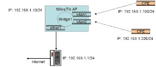
In this, the simplest setup we will create a dual access point (i.e. two radios, both set as an AP) and bridge all the interfaces. The internet is accessed through a server connected to the wired interface.
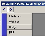
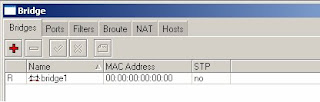
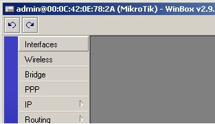
1) Select Bridge
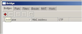
2) Click on the red ‘+’ to add a new bridge
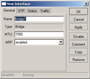
3) Accept all defaults and click on ok
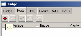
4) Click on the Ports tab
5) Click on the red ‘+’ to add a new port
6) Select Interface -> ether1, Bridge -> bridge1
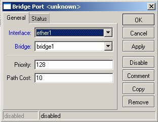
7) Click on the red ‘+’ again. This time select Interface -> wlan1, Bridge -> bridge1
8) Click on the red ‘+’ again. This time select Interface -> wlan2, Bridge -> bridge1
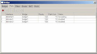
9) Close the Brige window
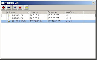
10) Click on IP - > Addresses
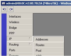
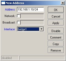
11) Click on the red’+’ to add an address
12) Enter the ip adderss 192.168.1.10/24 in the address field
13) In the interface drop down list box select bridge 1, the click on ok
*NOTE* All address formats in MikroTik are in address/subnet format, i.e. 192.168..1.1/24. For a more detailed explanation of this notation please see the appendix at the end of this document.
14) Close the Address List dialog box
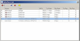
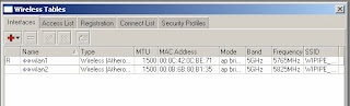
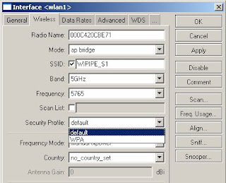
15) Select Interfaces
16) Double click on wlan1 to configure
17) Click on the wireless tab
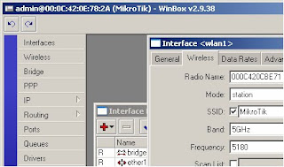
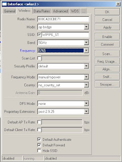
18) In the Mode drop down select ap bridge
19) Enter the desired SSID in the SSID field
20) In the Band drop down select either 5GHz or 2.4GHz-B
*NOTE* Wi-Pipe recommends using 802.11b only at 2.4 GHz as this standard has more robust signals *NOTE* Wi-Pipe recommends not using the same SSID on multiple AP’s as this can cause circular networks. These will cause error’s in your network and may prevent you from accessing your AP remotely.
21) In the Frequency field enter the desired frequency
22) Click on ok to save changes
23) Repeat for wlan2 (remember not to use the same SSID on both radio’s)
24) Select wlan1 and click on the blue to enable the interface
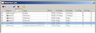
25) Select wlan2 and click on the blue to enable the interface
26) Close the Interface List window
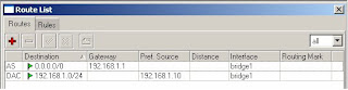
27) Select IP -> Routes
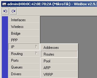
28) Click on the red ‘+’ to add the default route
29) In the destination field enter the address 0.0.0.0/0 (this is the notation for the default route)
30) In the gateway field in the ip address 192.168.1.1
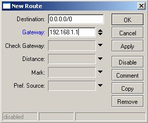
31) Click on ok to save changes
3. MikroTik Routed Setup
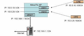
This guide highlights the differences between a bridged and a routed setup. Note this assumes you have not created the bridge and have not yet assigned an ip address to any interface.
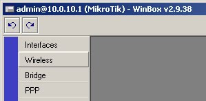
1) Click on IP -> Address
2) Click on the red ‘+’ to add an address
3) Enter the ip address 192.168.1.10/24, Interface -> ether1
4) Click on the red ‘+’ to add another address
5) Enter the ip address 10.0.10.1/24, Interface -> wlan1
6) Click on the red ‘+’ to add another address
7) Enter the ip address 10.0.20.1/24, Interface -> wlan2
8) Click on IP -> Routes and add 192.168.1.1 as the default route as per steps 27 to 31 above.
9) Click on IP -> Firewall
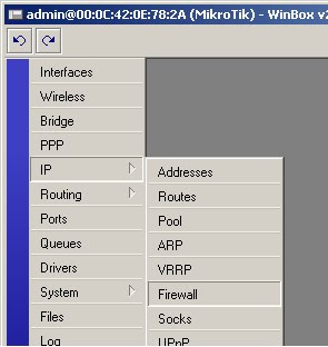
10) Click on the NAT tab
11) Click on the red ‘+’ to add a new NAT rule
12) Select Chain -> srcnat, Out Interface -> ether1
13) Click on the action tab
14) Select masquerade from the Action list box
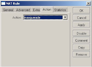
15) Click on ok to save
4. Adding WPA / WPA2 Security to your AP
1) Click on the wireless button
2) Click on the Security Profiles tab
3) Click on the red ‘+’ to add a new profile
4) Enter a name for the profile in the name field
5) Enter the WPA pass phrase in the WPA pre-shared key field
6) Enter the WPA2 pass phrase in the WPA2 pre-shared key field
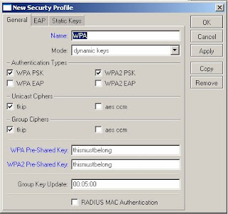
7) Click on ok to save
8) Click on the Interfaces tab
9) Double click on wlan1 to configure
10) Click on the wireless tab
11) In the security drop down select the new security profile
12) Click on ok to save
5. Setting up a WDS Bridge 1) Click on Bridge
2) Click on the red ‘+’ to add a new bridge
3) Enter details and click on ok
4) Click on Wireless
5) Double click on the wireless interface to configure
6) Select the wireless tab
7) In the mode drop down select bridge
8) In the band drop down select 5GHz or 2.4GHz-b as appropriate
9) In the Frequency enter the desired frequency
10) Click on the WDS tab
11) In the WDS mode tab select static
12) In the WDS default bridge drop down select the bridge created in step 2 above
13) Check the WDS Ignore SSID check box
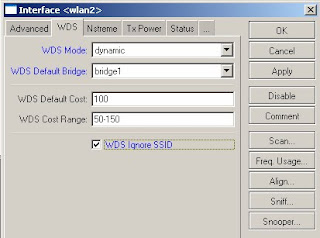
14) Click on ok to save changes
15) Click on the red ‘+’ and select WDS to add a new WDS interface
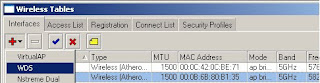
16) Click on the WDS tab
17) From the Master Interface tab select the desired wireless interface
18) Enter the MAC address of the other side of the link in the WDS address field
19) Click on ok to save
20) Repeat steps on second AP to create the bridge connection.
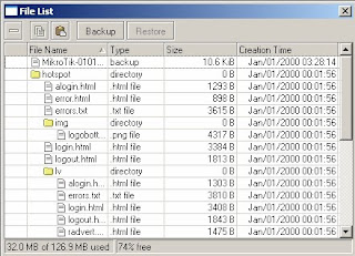
6. Backing up and Restoring AP configurations
To backup your configuration :
1) Click on files
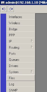
2) Click on backup
3) The system configuration will automatically be saved
4) To download the file, ftp to the router and download the file
To restore your configuration :
1) Open an ftp connection to the router and upload the configuration file
2) Click on files
3) Select the backup file and click on restore
7. Appendix C: Trouble Shooting
Winbox unable to find router locally connected to PC
Remedial steps :
- Ensure router is powered up
- Ensure router has fully booted, this can take more than 60 seconds
- If router has ip address ensure PC has an ip address on same subnet
- Ensure cross over cable is used from PoE injector to PC
- Ensure the cross over cable is not damaged
- Check the PC shows the Ethernet port has a connection. To do this start a command prompt. At the command prompt enter the command ‘ipconfig’. If ‘Media Disconnected’ is displayed, check all cables for damage.
- Ensure no firewalls etc. are running on the PC which would prevent it from accessing the router on all ports
- Attempt the same operation on a separate PC
If after performing all of the above steps you still cannot access the AP, fill out the RMA form http://www.wi-pipe.com/docs/Returns%20Form.pdf and return to Wi-Pipe for further investigation. Wi-Pipe will check the unit once received and report on whether the unit is faulty or not.
Winbox connects to router, and then immediately disconnects
Remedial steps :
- Try to connect by entering the ip address rather than the MAC address of the router into the Winbox connection screen
- Deselect the secure mode check box before connecting to the router
- Ensure the PC does not have an enabled wireless interface. If it does, disable the wireless interface and attempt to connect again
- Attempt the same operation of a separate PC
If after performing the above steps you still cannot access the AP perform either of the following steps :
- Download and start PuTTy (http://the.earth.li/~sgtatham/putty/latest/x86/putty.exe)
- Enter the AP’s ip address and click on open
- Enter login of admin and press enter
- If asked for a password leave blank and hit enter
- Reset the system by entering the command /system reset at the command prompt
- When asked are you sure, select y and hit enter
- When the system has been reset, try and access it using Winbox again
If after performing all of the above steps you still cannot access the AP, fill out the RMA form http://www.wi-pipe.com/docs/Returns%20Form.pdf and return to Wi-Pipe for further investigation. Wi-Pipe will check the unit once received and report on whether the unit is faulty or not.
AP Reboots erratically
This can be cause by many wireless interfaces having the same SSID causing many circular networks, poor power supply or board malfunction.
Remedial actions:
- Select Wireless
- Select each of the wireless interfaces and click on the red ‘x’ to disable them
- Wait to see if router reboots. If not, amend the SSID’s so they are not all the same
If after performing all of the above steps you still cannot access the AP, fill out the RMA form http://www.wi-pipe.com/docs/Returns%20Form.pdf and return to Wi-Pipe for further investigation. Wi-Pipe will check the unit once received and report on whether the unit is faulty or not.
Other Issues
If you have any other problems with you AP, please main details of the problem to info@wi-pipe.com. Include in the mail which of the setup’s above you were attempting, symptoms and as many screen shots as possible, especially the Status tab from the wireless configuration menu.
8. Appendix D: Further Information
If you require further assistance it can be found at :
Manuals
http://www.mikrotik.com/testdocs/ros/2.9/
MikroTik FAQ
http://wiki.mikrotik.com/wiki/MikroTik_RouterOS_Frequently_Asked_Questions_-_FAQ
MikroTik Forum
http://forum.mikrotik.com/
MikroTik Support
Support@mikrotik.com
If you would like guidance on more complicated setups please contact Wi-Pipe at + (0) 51 387 753 or info@wi-pipe.com
Winbox : http://www.mikrotik.com/download/winbox.exe
Neighbour Viewer : http://www.mikrotik.com/download/neighbour.zip
Dude : http://www.mikrotik.com/dude/
PuTTy : http://the.earth.li/~sgtatham/putty/latest/x86/putty.exe
** READ THIS FIRST **
The full version of this document can be downloaded from the Mikrotik section of www.wi-pipe.com It contains important information, setup guides and support for this AP. If contacting Wi-Pipe for support please indicate which of the provided setups you are using and confirm you have completed the appropriate Troubleshooting actions.*NOTE* : Wi-Pipe strongly recommend users configure and test their setup before installing this equipment.
The full version of this document contains the following sections:
1. ACCESSING THE MIKROTIK AP
2. MIKROTIK BRIDGED AP SETU
3. MIKROTIK ROUTED SETUP
4. ADDING WPA / WPA2 SECURITY TO YOUR AP
5. SETTING UP A WDS BRIDGE
6. BACKING UP AND RESTORING AP CONFIGURATIONS
7. APPENDIX C: TROUBLE SHOOTING
8. APPENDIX D: FURTHER INFORMATION
1. Accessing the MikroTik AP
1) Power up your MikroTik AP
2) Connect the AP directly to a PC using a cross over cable, or directly to a hub / switch
3) Run Winbox
4) Click on the ‘…’ button to view connected MikroTik devices

5) Select the device and click on connect

6) You are now connected to your MikroTik AP

Once you have assigned the AP an ip address it can also be accessed using PuTTY.
2. MikroTik Bridged AP setup

In this, the simplest setup we will create a dual access point (i.e. two radios, both set as an AP) and bridge all the interfaces. The internet is accessed through a server connected to the wired interface.
1) Select Bridge

2) Click on the red ‘+’ to add a new bridge

3) Accept all defaults and click on ok

4) Click on the Ports tab

5) Click on the red ‘+’ to add a new port

6) Select Interface -> ether1, Bridge -> bridge1

7) Click on the red ‘+’ again. This time select Interface -> wlan1, Bridge -> bridge1
8) Click on the red ‘+’ again. This time select Interface -> wlan2, Bridge -> bridge1

9) Close the Brige window
10) Click on IP - > Addresses

11) Click on the red’+’ to add an address
12) Enter the ip adderss 192.168.1.10/24 in the address field
13) In the interface drop down list box select bridge 1, the click on ok
*NOTE* All address formats in MikroTik are in address/subnet format, i.e. 192.168..1.1/24. For a more detailed explanation of this notation please see the appendix at the end of this document.

14) Close the Address List dialog box
15) Select Interfaces

16) Double click on wlan1 to configure

17) Click on the wireless tab

18) In the Mode drop down select ap bridge
19) Enter the desired SSID in the SSID field
20) In the Band drop down select either 5GHz or 2.4GHz-B
*NOTE* Wi-Pipe recommends using 802.11b only at 2.4 GHz as this standard has more robust signals *NOTE* Wi-Pipe recommends not using the same SSID on multiple AP’s as this can cause circular networks. These will cause error’s in your network and may prevent you from accessing your AP remotely.
21) In the Frequency field enter the desired frequency
22) Click on ok to save changes

23) Repeat for wlan2 (remember not to use the same SSID on both radio’s)
24) Select wlan1 and click on the blue to enable the interface

25) Select wlan2 and click on the blue to enable the interface
26) Close the Interface List window
27) Select IP -> Routes

28) Click on the red ‘+’ to add the default route
29) In the destination field enter the address 0.0.0.0/0 (this is the notation for the default route)
30) In the gateway field in the ip address 192.168.1.1

31) Click on ok to save changes

3. MikroTik Routed Setup

This guide highlights the differences between a bridged and a routed setup. Note this assumes you have not created the bridge and have not yet assigned an ip address to any interface.
1) Click on IP -> Address
2) Click on the red ‘+’ to add an address
3) Enter the ip address 192.168.1.10/24, Interface -> ether1
4) Click on the red ‘+’ to add another address
5) Enter the ip address 10.0.10.1/24, Interface -> wlan1
6) Click on the red ‘+’ to add another address
7) Enter the ip address 10.0.20.1/24, Interface -> wlan2

8) Click on IP -> Routes and add 192.168.1.1 as the default route as per steps 27 to 31 above.
9) Click on IP -> Firewall

10) Click on the NAT tab
11) Click on the red ‘+’ to add a new NAT rule
12) Select Chain -> srcnat, Out Interface -> ether1

13) Click on the action tab
14) Select masquerade from the Action list box

15) Click on ok to save
4. Adding WPA / WPA2 Security to your AP
1) Click on the wireless button

2) Click on the Security Profiles tab

3) Click on the red ‘+’ to add a new profile
4) Enter a name for the profile in the name field
5) Enter the WPA pass phrase in the WPA pre-shared key field
6) Enter the WPA2 pass phrase in the WPA2 pre-shared key field

7) Click on ok to save
8) Click on the Interfaces tab
9) Double click on wlan1 to configure
10) Click on the wireless tab
11) In the security drop down select the new security profile
12) Click on ok to save

5. Setting up a WDS Bridge 1) Click on Bridge
2) Click on the red ‘+’ to add a new bridge
3) Enter details and click on ok
4) Click on Wireless
5) Double click on the wireless interface to configure
6) Select the wireless tab
7) In the mode drop down select bridge
8) In the band drop down select 5GHz or 2.4GHz-b as appropriate
9) In the Frequency enter the desired frequency
10) Click on the WDS tab
11) In the WDS mode tab select static
12) In the WDS default bridge drop down select the bridge created in step 2 above
13) Check the WDS Ignore SSID check box

14) Click on ok to save changes
15) Click on the red ‘+’ and select WDS to add a new WDS interface

16) Click on the WDS tab
17) From the Master Interface tab select the desired wireless interface
18) Enter the MAC address of the other side of the link in the WDS address field
19) Click on ok to save
20) Repeat steps on second AP to create the bridge connection.
6. Backing up and Restoring AP configurations
To backup your configuration :
1) Click on files

2) Click on backup

3) The system configuration will automatically be saved
4) To download the file, ftp to the router and download the file
To restore your configuration :
1) Open an ftp connection to the router and upload the configuration file
2) Click on files
3) Select the backup file and click on restore
7. Appendix C: Trouble Shooting
Winbox unable to find router locally connected to PC
Remedial steps :
- Ensure router is powered up
- Ensure router has fully booted, this can take more than 60 seconds
- If router has ip address ensure PC has an ip address on same subnet
- Ensure cross over cable is used from PoE injector to PC
- Ensure the cross over cable is not damaged
- Check the PC shows the Ethernet port has a connection. To do this start a command prompt. At the command prompt enter the command ‘ipconfig’. If ‘Media Disconnected’ is displayed, check all cables for damage.
- Ensure no firewalls etc. are running on the PC which would prevent it from accessing the router on all ports
- Attempt the same operation on a separate PC
If after performing all of the above steps you still cannot access the AP, fill out the RMA form http://www.wi-pipe.com/docs/Returns%20Form.pdf and return to Wi-Pipe for further investigation. Wi-Pipe will check the unit once received and report on whether the unit is faulty or not.
Winbox connects to router, and then immediately disconnects
Remedial steps :
- Try to connect by entering the ip address rather than the MAC address of the router into the Winbox connection screen
- Deselect the secure mode check box before connecting to the router
- Ensure the PC does not have an enabled wireless interface. If it does, disable the wireless interface and attempt to connect again
- Attempt the same operation of a separate PC
If after performing the above steps you still cannot access the AP perform either of the following steps :
- Download and start PuTTy (http://the.earth.li/~sgtatham/putty/latest/x86/putty.exe)
- Enter the AP’s ip address and click on open
- Enter login of admin and press enter
- If asked for a password leave blank and hit enter
- Reset the system by entering the command /system reset at the command prompt
- When asked are you sure, select y and hit enter
- When the system has been reset, try and access it using Winbox again
If after performing all of the above steps you still cannot access the AP, fill out the RMA form http://www.wi-pipe.com/docs/Returns%20Form.pdf and return to Wi-Pipe for further investigation. Wi-Pipe will check the unit once received and report on whether the unit is faulty or not.
AP Reboots erratically
This can be cause by many wireless interfaces having the same SSID causing many circular networks, poor power supply or board malfunction.
Remedial actions:
- Select Wireless
- Select each of the wireless interfaces and click on the red ‘x’ to disable them
- Wait to see if router reboots. If not, amend the SSID’s so they are not all the same
If after performing all of the above steps you still cannot access the AP, fill out the RMA form http://www.wi-pipe.com/docs/Returns%20Form.pdf and return to Wi-Pipe for further investigation. Wi-Pipe will check the unit once received and report on whether the unit is faulty or not.
AP Reboots erratically
This can be cause by many wireless interfaces having the same SSID causing many circular networks, poor power supply or board malfunction.
Remedial actions:
- Select Wireless
- Select each of the wireless interfaces and click on the red ‘x’ to disable them
- Wait to see if router reboots. If not, amend the SSID’s so they are not all the same
If after performing all of the above steps you still cannot access the AP, fill out the RMA form http://www.wi-pipe.com/docs/Returns%20Form.pdf and return to Wi-Pipe for further investigation. Wi-Pipe will check the unit once received and report on whether the unit is faulty or not.
Other Issues
If you have any other problems with you AP, please main details of the problem to info@wi-pipe.com. Include in the mail which of the setup’s above you were attempting, symptoms and as many screen shots as possible, especially the Status tab from the wireless configuration menu.
8. Appendix D: Further Information
If you require further assistance it can be found at :
Manuals
http://www.mikrotik.com/testdocs/ros/2.9/
MikroTik FAQ
http://wiki.mikrotik.com/wiki/MikroTik_RouterOS_Frequently_Asked_Questions_-_FAQ
MikroTik Forum
http://forum.mikrotik.com/
MikroTik Support
Support@mikrotik.com
If you would like guidance on more complicated setups please contact Wi-Pipe at + (0) 51 387 753 or info@wi-pipe.com
Subscribe to:
Posts (Atom)